Low Level Quadruped Gait
ProjectFor this project, I developed low level control of a Unitree Go1 quadruped robot using ROS 2. This implements a trotting gait that is capable of walking forwards, backwards, left, and right. Parameters such as the step length, height, and speed are configurable. Additionally, I developed a custom stand-up and lie-down procedure.
Generating Feet Trajectories
The trajectory that the robot’s foot should follow needs to be smooth and continuous. A common method to generate such paths is Bézier curves, which have been used in similar quadruped walking gaits such as the MIT Mini Cheetah. A Bézier curve \(B(t)\) for \(t \in [0, 1]\) can be generated from a set of control points \(P_1, \dots P_n\) via the following explicit definition.
\[B(t) = \sum_{i = 0}^n \begin{pmatrix} n \\ i \end{pmatrix} (1-t)^{n-i}t^i P_i\]I followed the MIT Mini Cheetah implementation and generated a Bézier curve with 12 control points. These form the “swing-phase” trajectory, or the portion of the gait where the foot is off the ground. They are parameterized by the variables listed in the table below. \(\text{stand}_{x,y}\) are the coordinates of the foot with respect to the hip joint when the robot is standing still. \(L_{span}\) is half of the “stroke length”, which is the distance traveled forward with each step. \(\Delta L\) and \(\delta L\) are small values that affect how quickly the velocity of the foot changes in the \(x\) direction. \(Y_{span}\) and \(\Delta Y\) affect the stepping height of the foot and how quickly the \(y\) velocity of the foot changes. More information on the details of these control points are found in the MIT Mini Cheetah paper.
| Index | Control X coordinate | Control Y coordinate |
|---|---|---|
| 0 | \(\text{stand}_x - L_{span}\) | \(\text{stand}_y\) |
| 1 | \(\text{stand}_x - L_{span} - \Delta L\) | \(\text{stand}_y + Y_{span}\) |
| 2, 3, 4 | \(\text{stand}_x - L_{span} - \Delta L - \delta L\) | \(\text{stand}_y + Y_{span}\) |
| 5, 6 | \(\text{stand}_x\) | \(\text{stand}_y + Y_{span}\) |
| 7 | \(\text{stand}_x\) | \(\text{stand}_y + Y_{span} + \Delta Y\) |
| 8, 9 | \(\text{stand}_x + L_{span} + \Delta L + \delta L\) | \(\text{stand}_y + Y_{span} + \Delta Y\) |
| 10 | \(\text{stand}_x + L_{span} + \Delta L\) | \(\text{stand}_y\) |
| 11 | \(\text{stand}_x + L_{span}\) | \(\text{stand}_y\) |
Finally, the “stance-phase” trajectory, or the portion of the gait where the foot is on the ground, is generated following a sinusoidal function connecting the two edges of the swing-phase Bézier curve. The amplitude of this function is a parameter known as \(\delta\), which related to the force of the foot pushing into the ground.
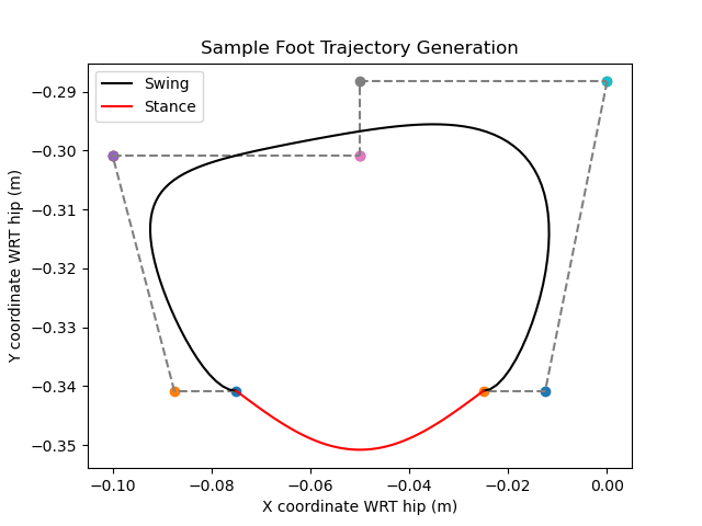
Foot trajectory generation showing Bezier control points
My ROS 2 package allows you to set these parameters for both forward (x) and lateral (z) stepping, allowing for different control points depending on which direction you are traveling in. This is important as the leg is less mechanically stable when the hip is extended, so smaller step lengths are required in this scenario.
Inverse Kinematics
I created a C++ library to handle the computation of inverse kinematics for the Unitree’s legs. Each leg is comprised of three revolute joints: hip, thigh, and calf. With the coordinate frame I defined (shown below), the hip joint can rotate about the x axis while the thigh and calf joints can rotate about the z axis. Therefore, for any desired foot position within the workspace of the robot, there are two solutions. Only one of these solutions is valid due to the joint limits.
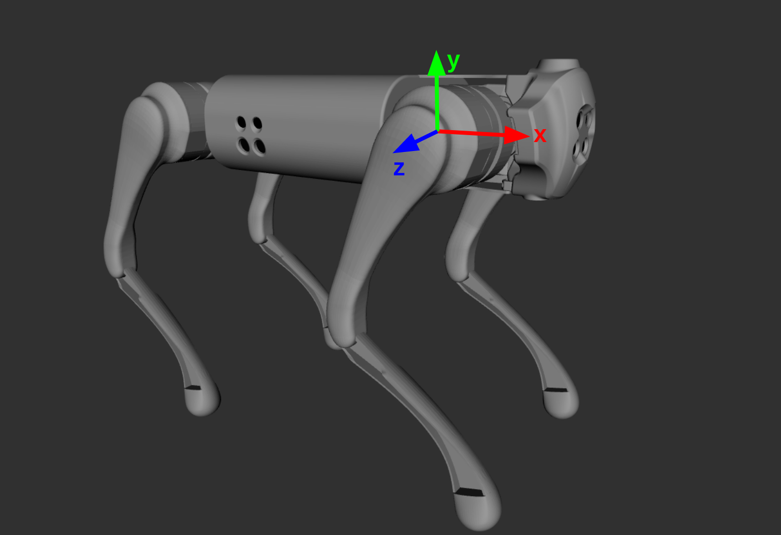
Coordinate frames I used for my inverse kinematics
From here, the necessary joint angles \((\theta_{hip}, \theta_{thigh}, \theta_{calf})\) to satisfy a \((x,y,z)\) foot position in this coordinate system are described below. \(L\) is the length of the thigh and calf segments, which is 0.213 m for the Unitree.
\[\theta_{hip} = \arctan\left(\frac{z}{y}\right)\] \[\theta_{thigh} = \arccos\left( \frac{\sqrt{x^2 + y^2 + z^2}}{2 L} \right) + \arctan\left(-\frac{x}{\sqrt{y^2 + z^2}}\right)\] \[\theta_{calf} = \arcsin\left( \frac{-x}{L} - \sin(\theta_{thigh}) \right) - \theta_{thigh}\]Gait Modulation
Once a desired foot trajectory is obtained, the next step is to set it with various offsets onto the four different feet. A standard quadruped gait is the “trot”, where the diagonal pairs of legs (front left + back right, front left + back left) move in tandem, 50% out of phase with each other. After using inverse kinematics to get the corresponding joint angles over time for one leg, I copy this trajectory onto the other legs with the appropriate offset to form the trot.
Low Level Control
I sent motor controls in a ROS node that published at 200 Hz. In this control loop, I specified the desired position of each of the 12 joints as a function of time. In order to quickly reach these positions with as little error as possible, I had to apply agressive PD constants of \(K_p = 90\) and \(K_d = 5\).
In order for the trot gait to be properly balanced, the swing and stance time should be evenly split per step. The control points that a leg follows over the course of one step, as well as what this looks like on all four legs after modulation, is shown below.
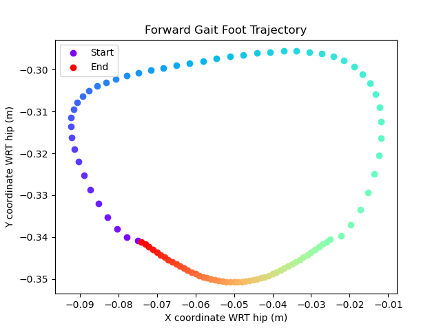
Desired trajectories for the front right foot for the forwards gait. Each point is evenly spaced in time, such that half of the points are in the swing and half are in the stance.
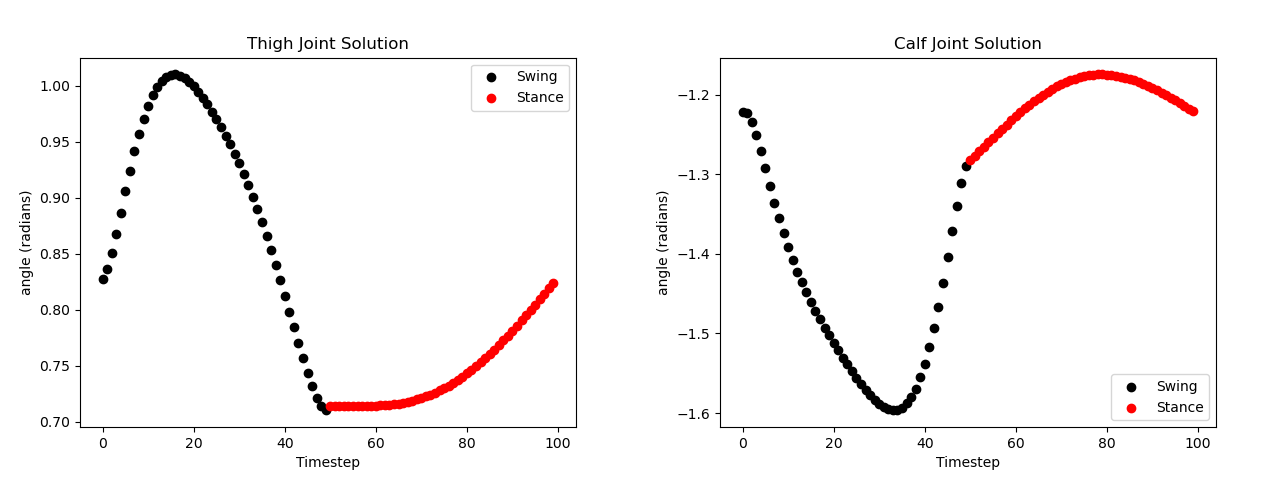
Inverse kinematics solutions for the hip and calf joints that satisfy the forward gait shown above. The hip joint stays constant at 0 for this movement.
Desired Forward Trot Gait
Finally, my standard gaits are generated in the forward and right directions. To travel backwards or left, I simply iterate the opposite direction through these trajectories as they are mostly symmetric.
Additional Work
Alongside fellow students Nick Morales, Marno Nel, and Ava Zahedi, I helped to upgrade the internal Jetson Nanos on the Unitree to Ubuntu 22.04, producing what we believe is first instance of this robot running ROS 2 Humble. Nick Morales and I developed an additional ROS 2 package designed to interface with the Unitree’s controls in both high level and low level mode, which formed the foundation of all of our projects involving this robot.
Future Work
Given more time with this project, I would have liked to implement some more complex walking behaviors, such as turning or walking in a circle. I am also interested in implementing more feedback control into my gaits by using the internal IMU (to detect when the robot is off balance, and apply a correction by pushing in the opposite direction) and/or the feet sensors (to more generally detect when to begin the stance portion of the step). This would add further stability to my gait, and in an extreme case could help the robot traverse more uneven ground.
More Details
The video below goes more in depth into the various strategies I employed to get a good walking gait (including some attempts that did not work too well)!